Power Electronics · Active research

725 W Phase-Shifted Full-Bridge Converter

A 324 V-to-12 V phase-shifted full-bridge converter with synchronous rectification, multilevel secondary architecture, and custom planar magnetics.
PLECSAnsys MaxwellFEMMPlanar Magnetics4-Layer PCB
Some technical details are intentionally withheld because this is ongoing research that may involve unpublished or patent-sensitive work.
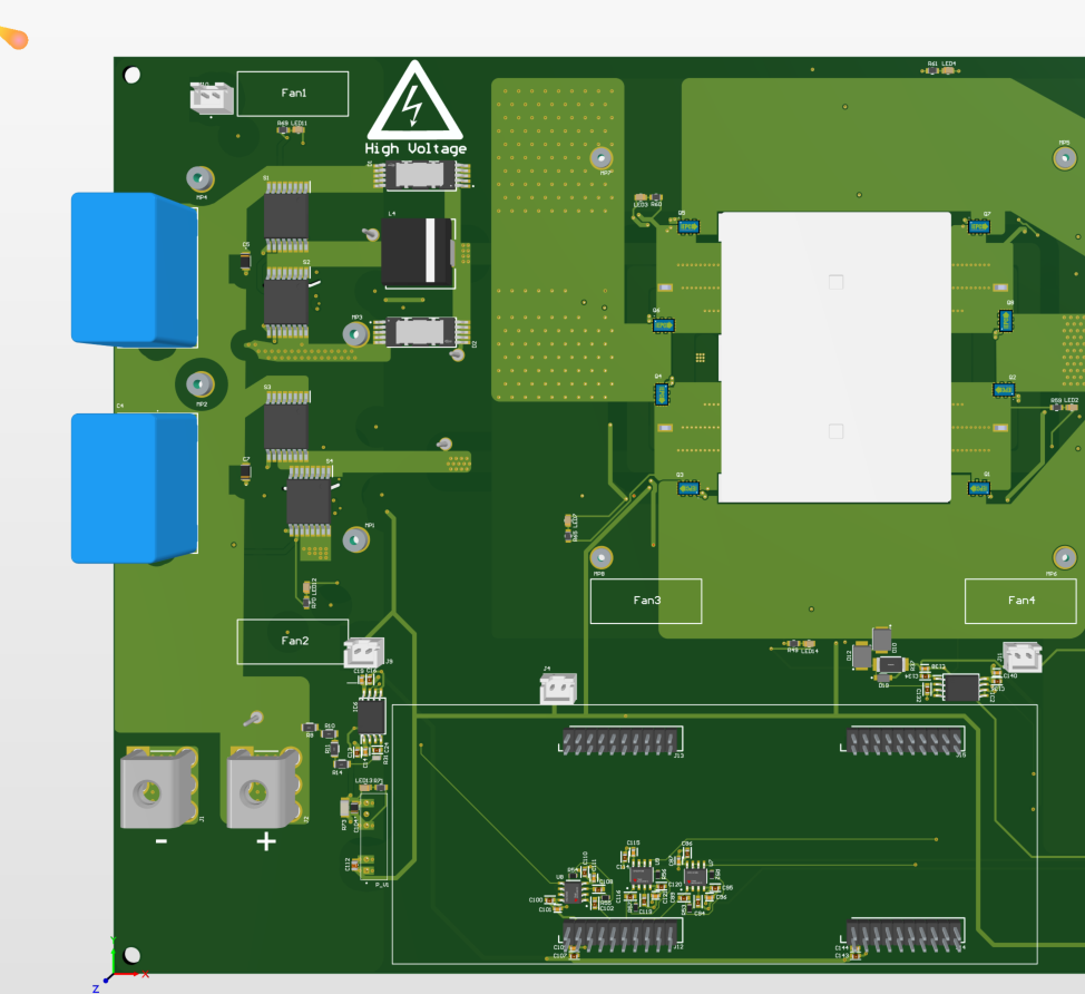
Altium 3D render of the 725 W phase-shifted full-bridge converter PCB

01

Objective

This University of Calgary research project explores a phase-shifted full-bridge converter with synchronous rectification. Its secondary-side architecture can be stacked to reduce output ripple and lower the current handled by an individual channel.

02

My contribution

Converter architecture and component-level design
PLECS switching and open-loop simulations
Open-loop modulation development
Analytical magnetics verification
FEMM and Ansys Maxwell electromagnetic analysis
Four-layer PCB design and routing

03

Design process

I moved between analytical calculations, switching simulation, electromagnetic finite-element analysis, and PCB implementation. This iterative workflow allowed control, losses, magnetics, and physical layout to inform one another before fabrication.

04

Technical challenges

The design had to resolve these system-level and implementation requirements.

Nominal 324 V input
12 V regulated output
725 W power target
Synchronous rectification
Stackable multilevel secondary
Custom planar transformer and inductor

05

Validation or results

The architecture, control approach, magnetics geometry, and PCB are in active development. The next major milestones are design review, fabrication, safe bring-up, and comparison of measured performance against simulation.

06

Images and diagrams

Selected project photographs and design captures. Open any image to inspect it at full resolution.
Top-down Altium 3D render of the phase-shifted full-bridge converter PCB
Full-board 3D render — power stages, planar magnetics, control interfaces, cooling provisions, and high-voltage layout
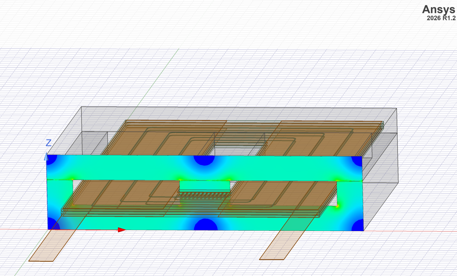
Ansys Maxwell finite-element model of the converter planar magnetic structure and windings
Ansys Maxwell model — finite-element analysis of the planar magnetic structure, winding geometry, and field distribution
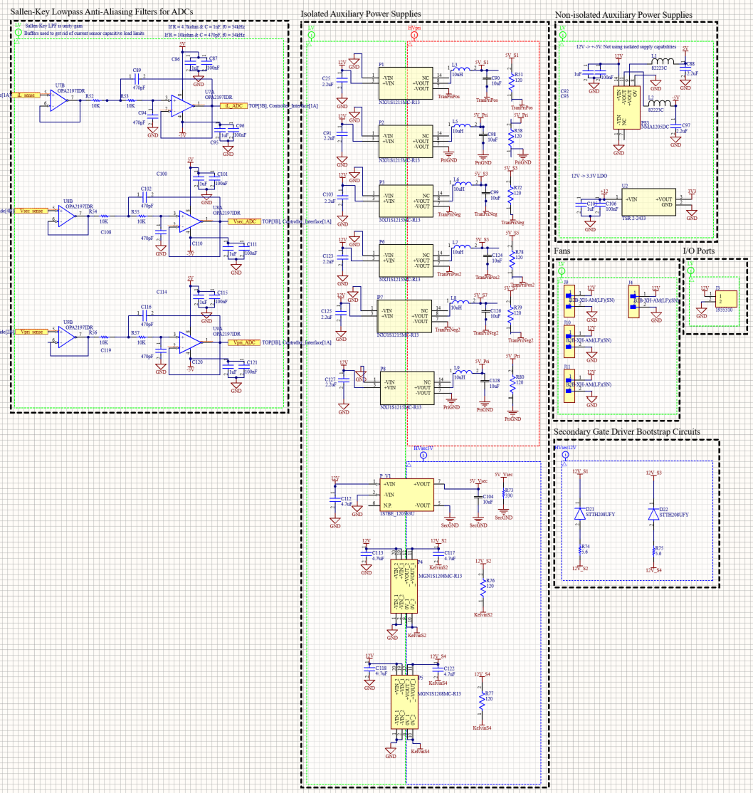
ADC filtering, auxiliary power supplies, cooling, and bootstrap schematic
Support circuitry — ADC anti-aliasing filters, isolated and non-isolated auxiliary supplies, fan connections, and gate-driver bootstrap circuits
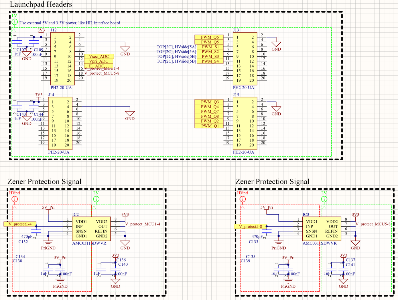
LaunchPad control headers and isolated protection-signal schematic
Control interface — LaunchPad PWM and ADC headers with isolated primary-side protection signals
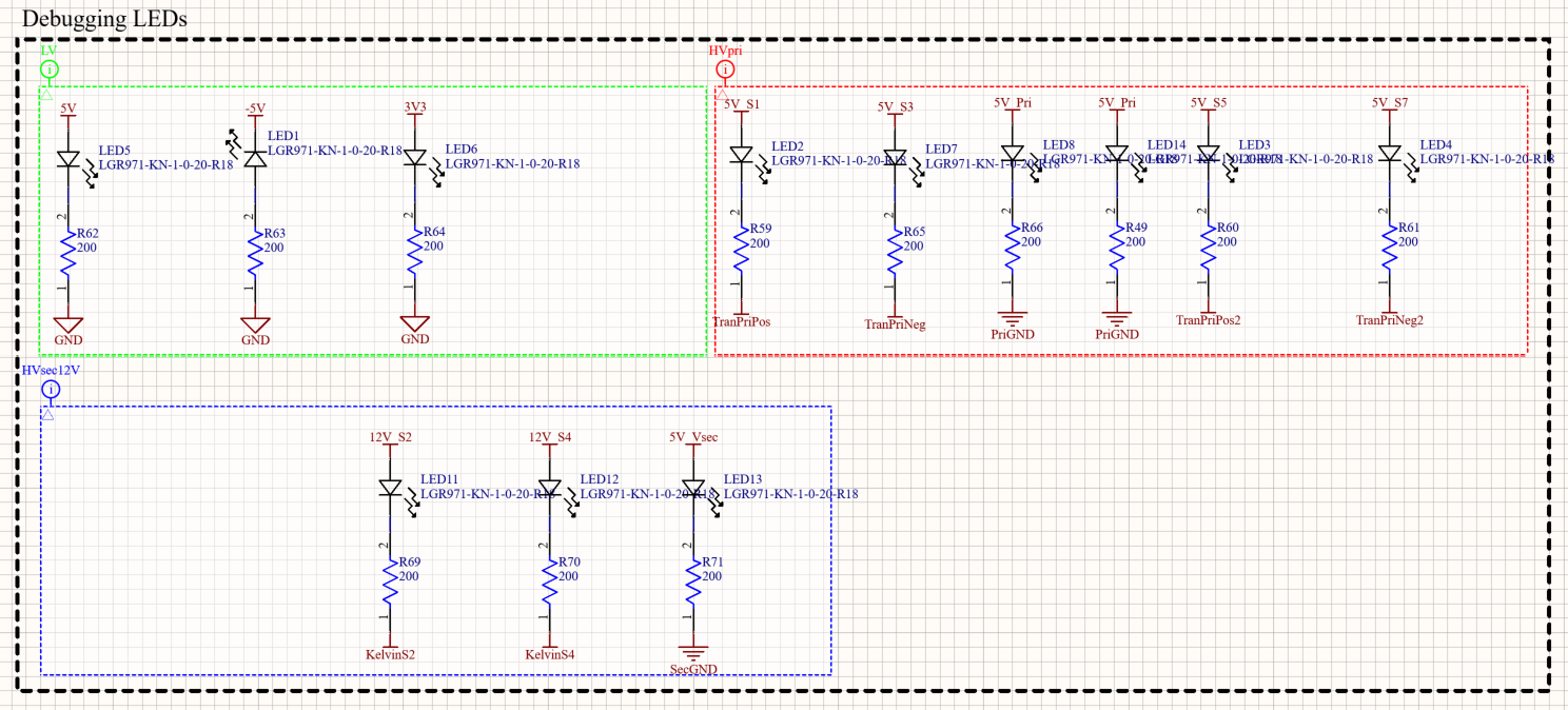
Debugging LED schematic for the converter power domains
Debugging indicators — visual monitoring of primary, secondary, and low-voltage power rails

07

Tools and technologies

PLECS · Ansys Maxwell · FEMM · Planar Magnetics · 4-Layer PCB

← Back to all projects